The Freerider Free Energy Inverter
The purpose of this prototype inverter is to test the possibility of extracting energy from the aetheric substrate through the hadron field theory. More to the point, a strong enough magnetic field within a metallic conductor (such as a metal plate or collector hit by high kinetic energy electrons), should de couple electron pairs in covalent state. Depending on the collector material density, temperature and kinetic energy of the impacting electrons, the decoupling could happen in hadronically favorable conditions such as to allow the breaking of the covalent bond at virtually no energy cost, or even at net energy gain thus allowing the measurement of a net negative voltage within the conductor that can be exploited for DC energy generation.
Introduction
In this paper we will present the possibility of an electric machine capable of achieving overrunity energies (energy output >> energy input).
The principle of operation of this electric machine was inspired by Edwin Gray inverter schematics and the possible operating principle (namely overrunity power outputs).
The subsequent advent in recent decades of hadronic physic has created a number of astonishing machines as already explained using sparks in hydrogen gasses or hydrocarbon fluids to achieve synthesis of neutrons or Magnegas fuels.
Hereby we shall propose one last type of spark within a metallic material, which is notably hard to achieve because electrons regrettably decay and converge down to thermal speeds when moving within a metallic matrix.
Nevertheless it is possible to have high kinetic energy electrons moving inside a metal if said electrons are “injected” into the matrix at high speeds (high MeV), so that they can penetrate the first few atomic layers of the solid metal collector at high energy before being decelerated down to thermal speeds inside the solid conductor.
Demystifying the covalent bond
In standard quantum chemistry electrons pair together to share common orbital paths within molecules or atoms, however electrons are also repelled because of coulomb repulsion, hence we have an array of strange “quantum” forces and explanations trying to reconcile coulomb repulsion with an attractive force and positive binding energy of electron pairs within some kind of orbital rail.
We should also note that even within the simplest molecule, the hydrogen one, quantum chemistry current covalent bond theory predicts it to be paramagnetic with even more embarrassing discrepancies for heavier and more complicate structures.
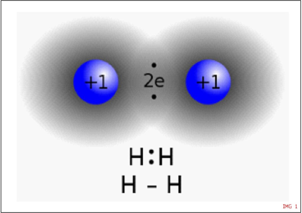
IMG 1: The covalent bond courtesy of Wikipedia. Protons are in the right position, as far apart as possible as dictated by Columbian repulsion but the electrons are “sticking together and chasing each other” despite said repulsion
Hadron mechanics on the other side, models other types of forces hereby referred to as “hadronic” ones modeled through a Hulten type potential, caused by the partial overlap or mutual penetration of electrons and protons, no longer to be considered as point like particle, but having a defined volume, thus capable of contact type interactions which are non hamiltonian.
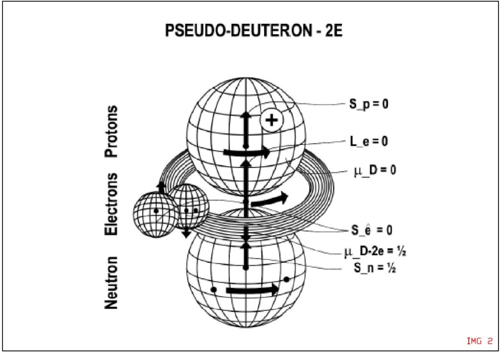
IMG 2: The covalent bond according to hadron mechanics. Two electrons on the left hand side are in partial mutual penetrations. Magnetic moments are anti parallel so to allow “gearing” of the particles and have a strong hadronic attraction between the two, whilst a parallel configuration would yield a strongly repulsive interaction which compounds to the Coulombian repulsion. Also note how electrons are no longer considered point like structures but have a physical volume of hyperdense media, another strong deviation from quantum theory where everything will look like a point particle without any volume nor possibility for a surface type interaction.
Making the theory work for us
One way to “decouple” electrons in a covalent bond state is to provide a strong enough magnetic field capable of forcing both electron magnetic axis toward a parallel (or non anti parallel) configuration. This strong magnetic field is provided by an electron moving into the metal at high kinetic energies as it happens in a spark gap emitter-collector configuration at sufficiently high voltages (IMG 3).
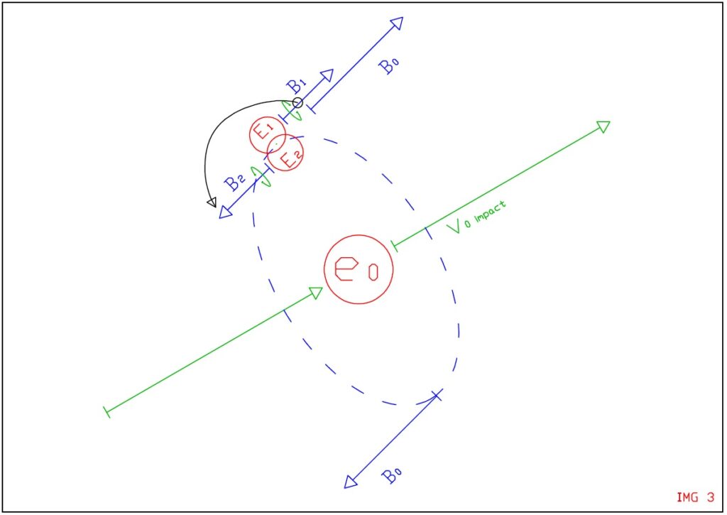
IMG 3: An high MeV electron generating a magnetic field and thus inducing a deformation on a nearby anti parallel covalent electron pair. We also assume that combustion processes are initiated by locally high enough kinetic energies (magnetic fields) locally capable of initiating decoupling of nearby covalent bonds, thus initiating the cascade reaction of combustion.
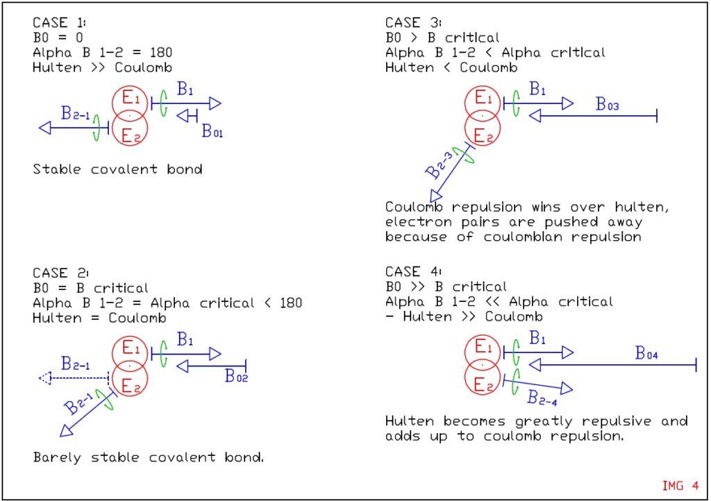
IMG 4: Covalent bond is strongly misaligned by an external magnetic field causing the hulten potential to reverse and become strongly repulsive.
When the two electrons are in perfect anti parallel alignment the 2 particles perfectly gear together and the covalent bond (hulten potential or hadronic covalent bond) is at its maximum (IMG 4, case 1).
When an external magnetic field twists the 2 electrons magnetic moments in a non perfectly parallel configuration then the covalent bond weakens (IMG 4, case 2).
If the magnetic field is stronger still then the misalignment increases and it causes an almost complete collapse of the hulten potential, at which point the coulomb repulsion is barely balanced by the hadronic covalent bond. The electron pair is about to break apart into a plasma state (IMG 4, case 3).
If the supplied magnetic field is strong and sudden enough, then the induced misalignment of the 2 electrons will happen so quickly that they will reach an almost parallel configuration before they have time to explode apart because of coulomb repulsion (IMG 4, case 4).
Of course when the alignment leans toward the parallel configuration then the hulten potential becomes negative, meaning it will push the two electrons apart even more strongly than the coulomb repulsion, thus inducing a net impulse energy extraction off the aetheric substrate.
The higher the spark gap voltage (Mev) the greater the number of electron pairs exploding in the hadronically excited state 4 as illustrated in IMG 5.
The covalent bond hadronic decoupling will be subsequently referred to as superelectric effect, in the sense that it adds thermal energy to the electron gas within the metallic conductor receiving the spark which in turn will exhibit an higher electronic gas pressure inside the metallic matrix thus appearing as negatively charged more than the dV induced by the incoming spark electrons.
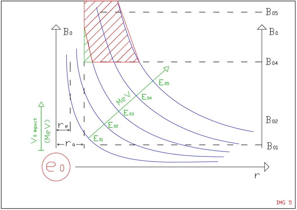
IMG 5: Induced magnetic field around impacting electron as a function of MeV and distance.
A minimum activation MeV energy is needed to achieve covalent bond hadronic decoupling.
In a nutshell, the breaking of the covalent bond will yield thermal energy available as kinetic energy of the two exploding electrons as opposed to requiring energy to separate the pair.
This excess thermal energy made available during the separation of the two electrons is compounded by the energy of the electron pair re-coupling together back into a covalent bond shortly after the impulse magnetic field disappears, meaning the electronic gas inside the matrix will substantially heat up thus causing an increased pressure of the electronic gas within the metal which results into a net negative voltage measurable within the irradiated conductor.
Testing the theory with a test circuit
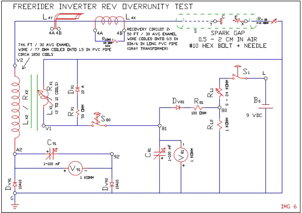
In this machine (IMG 6) one or more electrons are emitted from the tip of the spark gap emitter E, accelerated within the high voltage spark gap and subsequently the electron is decelerated within the metallic matrix of the collector C.
Spark gap could be in vacuum or air.
Collector design
The spark gap is powered by an HV coil intermittently powered by condenser C81/switch S80 causing only one controlled spark at the time across the gap.
The collector is a straight plate type. It can be an hex bolt of preferably low density metallic materials (ie aluminum) to allow for spark gap distance regulation. It temporarily charges at high positive voltages thus drawing electrons from the emitter needle.
The spark gap also features a thick metallic shield, this is to protect operators and personnel from harmful X-Ray radiation generated by the spark gap operations.
Emitter design
The emitter is a simple needle tip connected to the ground. The tip can be warmed up through a candle or nearby resistor like in Edwin Gray emitter patent to enhance thermionic effect and emission of electrons. Alternatively a resistor could be used to minimize emission for testing purposes.
To note that Edwin Gray spark tube patent incorporated a resistor on the emitter tip obviously to enhance thermionic effect during steady state operation of the spark gap but this were advanced designs aiming at product maturity and greater efficiency.
Main controls
The sparks could be timed through an astable multivibrator which allows for recharge of the primary coil condenser C81 before allowing it to discharge through the LV coil, however in this case we prefer to use a manual switch to test one spark event at a time.
An additional voltage regulator (RL1 and C81 variable) controls the voltage and coulombs available for each spark energy.
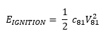
The energy spent on each spark is effectively and precisely metered as:
The energy recovery circuits
The energy recovery circuit is at the bottom left corner and is made by Condenser C91 and the load resistance R load.
During the spark events electrons are drawn from tip E into collector C and these electrons (plus a certain surplus because of the superelectric effect described above) are allowed to escape the conductor through diode Dv91.
However when the superelectric effect fades then conductor C / Lx2 / Rx2 will find itself in electron deficit and it will strongly charge itself positively.
The presence of condenser C91 allows for this voltage energy to be stored and slowly released to the load resistance (our volt meter V91).
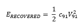
The energy recovered on this side of the circuit is also easily measured as:
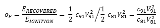
Measuring the overrunity factor
The cycle overrunity factor can subsequently be measured as the ratio between:
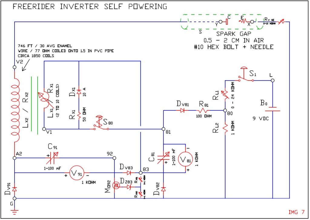
A modified version of the overrunity test circuit is tentatively presented in IMG 7 to loop back some of the electrostatic energy into condenser C81 and therefore operate the circuit without a battery energy source for the spark ignition.
By varying the condenser C81 capacity, voltage 81 and primary coil number it is possible to modulate the impact energy of electrons up to the point where critical Mev spark energy is reached capable to trigger superelectric effects on a broad enough volumes of space inside the metal (ref fig 5).
This superelectric effect should then yield a certain overrunity factor as per equation above which is fairly easy to measure experimentally.
In the case of C81 = C91 then the overrunity factor becomes equal to (V91/V81)^2.
The measurement of a voltage in V91 greater than V81 would effectively mean a breach of the energy conservation principle in favor of novel hadronic theories and the possibility to generate virtually unlimited electric energy by means of simple solid state electronic devices.
Testing the hypothesis of magnetic monopoles and magnetic currents
Additional recovery circuit test the possibility of anomalous magnetic fields and currents as described in certain patents and articles describing the Edwin Gray machines.
The energy recovery circuit 2 tests the possibility of magnetic monopole currents being generated during spark gap operation.
The inductor L4x is a wire coiled around the HV cable connecting to the spark gap collector C or else an air core inductor with wire Y-V2 passing through its axis.
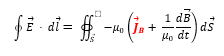
This inductor design is unprecedent in electronic applications since the magnetic current element J B has always been neglected and set to ZERO within Maxwell equations but it is hereby assumed to be NON ZERO, hence the unusual design of inductor L4x and L4y which we shall call Gray transformers in accordance to.
The low voltage coil of the gray transformer L4 should generate a pulsed DC voltage between its terminals 4A and 4B which powers an additional resistive load.
Controlling the power output
There are only 3 parameters to be controlled: the spark gap timing (frequency) and the charge voltage of condenser C81 as well as the capacity of C81.
Increasing the frequency increases the average power to the load whilst increasing the voltage ultimately increases the specific energy (joule) for each spark cycle AKA overrunity factor.
BJT vs FET
The use of solid state electronic components is tempting due to their simplicity and the capability to create complex and accurate controls (namely increasing the operating frequency of the system, thus the power output available).
However it must be noted that because of the peak voltages and high currents locally induced during normal operation of the system, the reliability and life expectancy of solid state transistors or diodes is suspected to be fairly low, thus the need to completely isolate the HV circuit from the LV circuit and ideally use mechanical contactors instead of solid state switches.
The use of switch S80 on the negative side of condenser C80 is to protect said condenser from overvoltages when the switch closes, since electrons through S80 will arc because of the high discharge current and the superelectric effect induced by said electrons could also damage the condenser.
In fact the original Edwin Gray patents used automotive style ignition coils (no solid state electronics), unfortunately nowadays automotive coils only have 3 terminals available so to push electrons out of the HV coil as opposed to pull electrons in to enhance electron kinetic energy on the collector, but they are a possible, robust way to build more reliable prototypes.
As a general rule, diodes shall be generously oversized, capacitors shall be enclosed to protect operator from possible explosion, mosfets shall be placed far from conductors and wires exposed to superelectric effect due to the gate low tolerance to overvoltages and the spark gap should feat some thick steel shielding to protect operator from x-ray emission during normal operation.